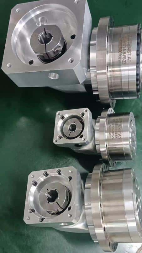
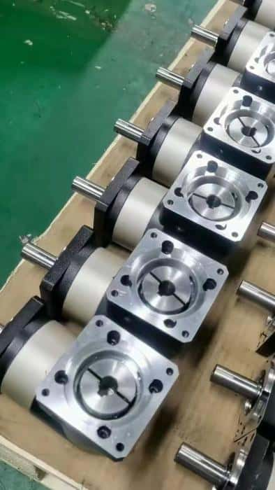
There are several key parameters to measure the performance of planetary gear reducers, including gear clearance, transmission efficiency, rated output torque, service life, gear ratio, operating noise, radial force, lateral force, and operating temperature. Among these, gear clearance is a critical parameter that directly affects the efficiency and service life of the gear. In order to help users use planetary gear reducers more effectively, this article analyzes the causes of the clearance in reducers and provides detailed instructions on how to adjust gear clearance accuracy correctly.
First, we can use a dial indicator to test the gear clearance, as follows:
Install a pair of gears correctly; fix one of the gears in place; the dial indicator touches the active gear near the pitch circle diameter (near the middle point of the tooth height), with the indicator direction as perpendicular as possible to the tooth profile; repeatedly rotate (swing) the active gear, and the dial indicator reading is the gear backlash for this pair of gears.The causes of gear clearance in planetary gear reducers are mainly related to the following two factors:
1. Gear accuracy
The accuracy of the gear is directly related to the gear processing technology, gear processing equipment, and raw materials. The higher the accuracy level of the gear processing, the higher the overall accuracy of the reducer.2. Assembly accuracy
Assembly accuracy is directly related to the technical skills of the assembly personnel, assembly tools, and inspection equipment.
Once you know the gear clearance testing method and the causes of the clearance, the next step is to figure out how to adjust it:
1. Gear clearance adjustment method:
In general, apply red lubricating oil (a mixture of red powder and engine oil) to the active bevel gear surface, and then rotate the active bevel gear by hand several times. Red spots will appear on the two working surfaces of the driven bevel gear.If the imprint on the working surface of the driven bevel gear is located in the middle of the tooth height and covers more than 60% of the tooth surface width, then it is the correct meshing. The correct meshing position can be obtained by adjusting the total thickness of the shims between the main reducer housing and the bevel gear housing (i.e. moving the position of the bevel gear).
2. Methods to avoid the generation of gear clearance:
As mentioned above, the causes of gear clearance are related to gear accuracy and assembly accuracy, both of which are the responsibility of the reducer manufacturer. Therefore, when purchasing planetary gear reducers, it is advisable to choose a reputable manufacturer in order to avoid this quality issue from the source.
 English
 Deutsch
 Русский
 Español


Quote Now